Thursday, December 5, 2019

Snow Loading for Trusses: Why Specifying a Roof Snow Load Isn’t Enough

bill-walton-quoteYou might wonder what a quote about winning basketball games could possibly have to do with snow loading on trusses.  As with basketball, the importance of close teamwork also applies to a project involving metal-plate-connected wood trusses – for the best outcome, the whole team needs to be on the same page. For purposes of this blog post, the team includes the Building Designer, the Truss Designer and the Building Official, and the desired outcome is not a win per se, but rather properly loaded trusses. Snow loading on trusses is one area where things may not always go according to the game plan when everyone isn’t in accord. This post will explain how to avoid some common miscommunications about truss loading.

Which snow loads are you specifying?

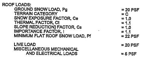
Like all other design loads that apply to trusses, snow loads are determined by the Building Designer and must be specified in the construction documents for use in the design of the building and the roof trusses. But sometimes the loads that are specified don’t provide enough information to ensure that the design will be correct for the specific circumstances. In the case of designs for snow loads, there needs to be a common understanding among all parties regarding the following:

  • Which snow load value is to be used as the uniform design load for the snow – a ground snow or a factored ground snow?
  • If it is a factored snow load, then how is the ground snow to be factored?
  • What other conditions need to be considered besides uniform load?
Sample Snow Load Specification

For example, say the Building Designer specifies that the trusses are to be designed for a 25 psf roof snow load. At first glance, this may appear to make things easier, since there is no need to convert the ground snow to a roof snow load. So what does the Truss Designer do with this load? There are a few different possibilities:

If unbalanced snow loading isn’t required or specified, the Truss Designer may enter the 25 psf snow load as a top chord live load (TCLL), set the load duration factor to 1.15 for snow, and turn snow loading off completely. Or the 25 psf snow load could be entered as a roof snow load with the unbalanced snow loading option turned off. Provided that no slope reduction factor gets applied to the specified roof snow load, both of these methods result in the same design. However, as discussed in my first blog post on snow loading for trusses, whenever a snow load is run as a roof live load rather than a snow load, it may not be clear to all parties involved what exactly the truss has been designed for, since there will be no notes indicating the snow design criteria on the truss design drawing.

If unbalanced snow loading is required, things get a bit trickier.  There are still two scenarios as to how the truss could be designed, but this time, the design results are different:

  • The truss could be designed based on the assumption that ground snow is being used as the roof design snow load (pg = 25 psf); or
  • The truss could be designed based on the assumption that the 25 psf roof snow load is a factored ground snow load, in which case a ground snow load is back-calculated using ASCE 7 based on the specified roof snow load (pg > 25 psf)

Therein lies the problem with specifying only a roof snow load. The determination of the drift load that is required for unbalanced snow load cases requires the use of the ground snow load, pg, not the roof snow load. If the ground snow load isn’t specified, then a ground snow load needs to be assumed – and the Truss Designer and the Building Designer may not be on the same page as it relates to this design assumption.

ASCE 7 Drift Height Calculation

Even when the specification is clear regarding ground snow vs. roof snow load and the applicable snow load reduction factors, there is still the question whether any other conditions need to be considered besides uniform load. This includes not only unbalanced snow loads on standard gable roofs, but also drifting on lower roofs or in valleys, sliding snow, and any other snow-loading and/or snow accumulation considerations. Since trusses are designed as individual planar components, snow-loading conditions that go beyond the simple unbalanced load case on either side of the ridge on gable roof trusses must be detailed by the Building Designer.

Snow accumulation requirements must be detailed by the Building Designer

As mentioned in a previous blog post, the truss industry’s Load Guide entitled Guide to Good Practice for Specifying & Applying Loads to Structural Building Components provides a tool to help Building Designers, Building Officials, Truss Designers and others more easily understand, define and specify loads for trusses. Similar to the wind-loading section discussed in that previous blog post, the Load Guide has an entire section on snow loading, how specific snow-loading provisions apply to trusses and how trusses are typically designed for snow loading within the truss design software.

Snow Load Worksheet from the Load Guide

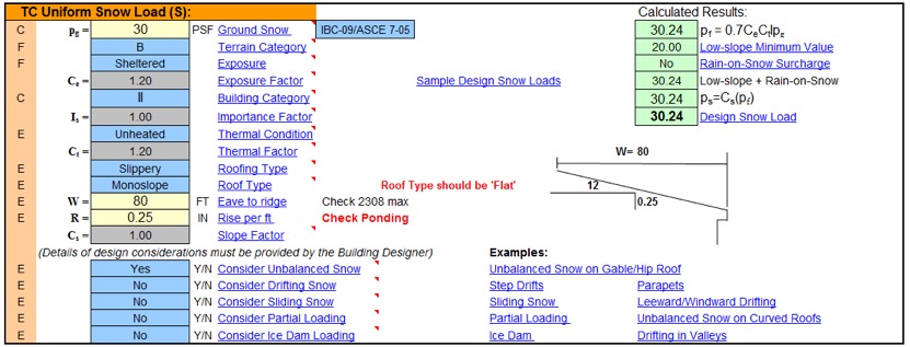
With printable worksheets that can be used to define the snow loads and examples of multiple snow- loading conditions on different roof and truss profiles, the Load Guide is an invaluable tool for getting everyone on the same page. That’s what I would call a win!

How do you ensure that your design team is all on the same page regarding the loading of trusses? What are the biggest challenges for designing truss loads in your jurisdiction? We’d love to hear your thoughts.

This blog post was originally published on January 7, 2017. 

The post Snow Loading for Trusses: Why Specifying a Roof Snow Load Isn’t Enough appeared first on Simpson Strong-Tie Structural Engineering Blog –.

from Simpson Strong-Tie Structural Engineering Blog – http://seblog.strongtie.com/2019/12/snow-loading-trusses-specifying-roof-snow-load-isnt-enough/

Wednesday, November 20, 2019

The Simpson Strong-Tie Excellence in Engineering Fellowship, A Grateful Adventure

Before starting my fellowship, a year seemed like a very long time to be away from my day-to-day life, my clients, and my comfort zone. I started with many questions about how I could support the Build Change team to make the biggest possible impact with this fellowship. Once I started, however, I found more than a great team; I found a family. I would like to start this blog by praising the support of every member of the teams that I worked with, including the Build Change headquarters staff, as well as the staffs of the programs in Colombia and the Philippines. 

With the staff of Build Change’s office in Colombia

Convincing people of something that is invisible, such as the risk of living in a potentially unsafe house, is like swimming upstream. Sometimes it’s hard to see the returns on all your invested effort. However, one of the immediate benefits that Build Change provides to homeowners is the peace of mind that comes from knowing that their families will be safe during an earthquake. Helping homeowners and their families stay optimistic about the future is real proof of resilience; this is the extraordinary quality we want to create in the houses Build Change constructs.  

Frustration is inevitable when you are creating social change, and this frustration requires constant injections of hope from Build Change’s leadership, both at the local and international levels. When you see the scope of the crisis of informal housing, it’s easy to become despondent.  But there’s a lot to be optimistic about. 

A moment of relaxation with Dr. Elizabeth Hausler, Founder & CEO of Build Change, and the team in the Philippines.

Before starting this adventure, my business was centered purely on the structure of buildings. Even if those buildings were designed for a particular purpose, such as schools in isolated regions of the country, I never directly got to know the people I impacted with my job. I will miss Build Change because it gave me an opportunity to meet homeowners and learn about their needs, desires, and limitations. I will miss this personal connection with the people I was working to help. Although the support I provided was mostly related to the development of technical resources, in the end, a family will be the beneficiary of my efforts.

My fellowship experience was completely positive; I had the chance to meet great people, travel, and do work I love while helping communities improve their houses. In Colombia, I played an essential role in the development of the new manual to guide the assessment and retrofitting of informal houses. This document was submitted to Colombia’s Seismic Engineering Society for approval. I also helped the Colombia Build Change team create a new set of construction drawings according to the updated manual, as well as construction specifications to be used by the Ministry of Housing in Colombia in the “Casa Digna, Vida Digna” (Decent House, Decent Life) program. This program aims to make 600,000 resilient home improvements by 2022. 

In the Philippines, I was involved in the development of a technical platform for the assessment and the retrofitting of houses using Fieldsight. The goal of this mobile application is to enable Build Change’s microfinance partners to quickly assess the potential of one-story unreinforced masonry houses for retrofitting. This information helps the microfinance partners determine their loan approvals. It was an exciting challenge, requiring a lot of creativity and XLS programming, to develop user-friendly yet powerful forms that could generate solutions consistent with reality.

Before I wrap up, I want to offer my sincere thanks to Simpson Strong-Tie for connecting me to Build Change and making this experience possible. Your collaboration and support have been immeasurable.  

For the next fellow, I hope you have an experience as fantastic as I did. This is a perfect opportunity to use engineering knowledge for the good of people that need it. Enjoy every moment. Unleash your creativity to find new and better solutions, and reach into your humanity to connect with the people who live in the homes you build.  


The post The Simpson Strong-Tie Excellence in Engineering Fellowship, A Grateful Adventure appeared first on Simpson Strong-Tie Structural Engineering Blog –.

from Simpson Strong-Tie Structural Engineering Blog – http://seblog.strongtie.com/2019/11/the-simpson-strong-tie-excellence-in-engineering-fellowship-a-grateful-adventure/

Wednesday, November 6, 2019

Trainer to the Pros — How Simpson Strong-Tie Educates the Industry

Did you know that Simpson Strong-Tie offers free education and training to the construction industry?

Indeed, we do. For several decades, Simpson Strong-Tie has made a commitment to supporting our industry, and each year we educate tens of thousands of industry pros — engineers, architects, dealers, contractors and building inspectors — about the latest building code updates and best construction practices.

Our regional training centers offer workshops providing solution options to meet current construction industry challenges, with instruction on proper specification, correct installation and the inspection of connectors and structural systems. Many of the courses include opportunities for hands-on installation and testing demonstrations of Simpson Strong-Tie products. Additionally, we offer courses on topics — such as changing construction practices, or building to resist seismic forces or high winds — of particular relevance to specific geographic regions.

This commitment to education sets us apart within the manufacturing industry, and it’s an aspect of our customer service in which we take great pride as a company.

Why does Simpson Strong-Tie offer training to construction industry professionals?

Simpson Strong-Tie has been designing and manufacturing construction solutions for more than sixty years, with the goal of helping people build safer structures. Construction is an industry we’re deeply committed to, and we take our responsibilities as a building manufacturer very seriously. All our training efforts are ultimately focused on improving construction quality and the overall strength and safety of structures.

More specifically, we want to make sure the right products are specified and that they’re installed correctly, for the safety of the building occupants and the reputation of all our partners — specifiers, contractors and dealers.

Besides all the good business reasons to build lasting relationships with our customers, we have a passion for education and feel an obligation to support the industry and communities that have contributed to our success over the decades.

What topics does Simpson Strong-Tie cover in its training?

We cover a very broad range of topics of use to designers, installers, building officials, and other construction professionals. What follows is a modest sample of current course offerings:

But really there’s no limit to the number. Our topics reflect the feedback of our customers. Where there’s a need, we create a course.

Is it easy for industry professionals to access training from Simpson Strong-Tie?

We do everything we can to make training as accessible as possible. We have regional training centers across North America, and we have specialists in every region who are available to visit your company for in-person instruction.

In addition to our live workshops and presentations, we also offer live and recorded webinars and a wide range of online courses that are available for credits.

What does the course participant gain from the training?

First of all, the training gives customers a complimentary and convenient source of practical knowledge about the finer points of their jobs.

Our courses are facilitated by knowledgeable instructors with a passion for providing substantive education, often in tandem with registered engineers who provide in-depth technical expertise in the subject matter. “The workshops are very interactive,” explains Charlie Roesset, Director of Training for Simpson Strong-Tie. “Depending on the course, students may have the opportunity to view product samples or take part in product testing and installations.”

“There’s no other manufacturer who provides such extensive training programs,” according to Roesset. “Specifiers and building officials have come to rely on these courses to keep abreast of the latest code updates and technical information.”

Furthermore, the courses provide an excellent means for customers to earn professional credits within their field.

Can participants receive PDHs and CEUs for completing courses?

Yes. Training participants receive a certificate of attendance with professional development hours (PDHs) at the end of each workshop, and may earn continuing education units (CEUs) by completing additional requirements, such as a test at the end of the course. All of our on-demand courses offer PDHs, and many offer CEUs, AIA Learning Units (LUs) and ICC CEUs.

Simpson Strong-Tie is a registered education provider with a number of industry organizations and associations including the American Institute of Building Design(AIBD), the American Institute of Architects (AIA), the International Code Council (ICC) and the International Association for Continuing Education and Training (IACET). Our courses are also accredited by a number of state or regional licensing organizations.

What is the cost of the courses?

Nothing! All our workshops, webinars and online courses are completely free of charge.

Why does Simpson Strong-Tie offer its training free of charge?

We believe it’s important that construction professionals understand our product solutions, their proper specification and installation, and their larger role in building strong, safe structures. We take pride in providing users not just with products, but with complete design and building solutions that include training and engineering support.

It’s one of the ways we try to give back to our customers, industry and communities.

What have participants had to say about the training we provide?

Response from participants in our courses has been very enthusiastic. Here’s a representative selection of their feedback:

“Todd was very thorough and knowledgeable. He understood our needs and interests and addressed those directly, without misusing our limited time.” – Gray H., structural engineer, Evansville, IN (Simpson Strong-Tie Anchor Designer Software— box-lunch product knowledge presentation)

“Absolutely impressed with the content, graphics, learning pace, and style. I love how individual issues are represented: with a graphic, photos, code references, and failure examples — all together. Wish all CE courses were like this!” – Daniel K., inspector, Zionsville, IN (Deck Inspection for New and Existing Construction— online)

“Simpson webinars have been very informative and are a valuable training tool for young engineers . . . please keep up the great work.” – Donald O., engineer, San Diego, CA (Upgrade Your Coiled Strap— webinar)

Where can I learn more about your training offerings?

To explore the range of our current offerings and register for a workshop or online course, visit training.strongtie.com/learn or contact your local Simpson Strong-Tie representative at (800) 999-5099to schedule a box-lunch presentation at your business.Have questions, or suggestions for new courses? Please email us at training@strongtie.com.

Thank you, and keep on learning!

The post Trainer to the Pros — How Simpson Strong-Tie Educates the Industry appeared first on Simpson Strong-Tie Structural Engineering Blog –.

from Simpson Strong-Tie Structural Engineering Blog – http://seblog.strongtie.com/2019/11/why-simpson-strong-tie-offers-free-education-and-training/

Wednesday, October 30, 2019

Adjustable Hanger or Custom Hanger — You Make the Call

It would be a lot simpler for designing engineers if structural connections were always for members at right angles to one another. Often, connections have to be designed for supported members that are at a skewed or sloped angle rather than perpendicular to the header. In these cases, the engineer will have to choose between a premanufactured adjustable hanger and a custom hanger. Simpson Strong-Tie offers both options, and in the following post, Randy Shackelford, P.E., discusses the various considerations that may affect a specifier’s choice.

It makes things easy for an engineer when the building being designed is rectangular. This allows you to make the connections between nice perpendicular members, and standard connectors and joist hangers are easy to specify.

But buildings are not always rectangular and connections are not always between perpendicular members. Non-perpendicular members can have a skewed connection, where the supported member is moved side to side from perpendicular; or a sloped connection, where the supported member slopes up or down from a standard horizontal orientation; or a combination of the two.

To help with these situations, Simpson Strong-Tie offers the option of either premanufactured adjustable hangers or custom-manufactured hangers. The choice may depend on the time frame in which the hanger is needed, the load demands that will be placed on the hanger, the cost of the hanger, or all of these.

Typical HWP manufactured sloped down, skewed right with type A hanger (joist end must be bevel-cut). This illustration shows the high side flush option where the top of the sloped member is flush with the top of the supporting beam.

If the demand load is low or an immediate solution is needed, Simpson Strong-Tie offers several adjustable hangers that can be skewed, sloped, or both in the field. Adjustable hangers are likely to be the most cost-effective option if they meet the load requirements of the connection.

Simpson Strong-Tie has recently revamped its offerings of adjustable joist hangers. The older versions of adjustable hangers, known as the LSU and LSSU series, required that the hanger be attached to the carrying member before installation of the carried joist. This required a disruption of the normal installation sequence in the field. Two new models of adjustable joist hangers have been developed that can be installed after the joist is placed on the supporting member.

For lighter loads, as in a rafter-to-hip connection, the newly developed LSSJ is an economical option. It installs on only one side so all the fastener holes are easily accessible. Because it doesn’t have a flange that extends behind the rafter or joist, it can be installed as a retrofit. It accommodates roof pitches from 0:12 to 12:12. The swivel seat provides the code-required bearing for the rafter/joist. Finally, note that the hanger comes in two models, LSSJR for skewed right, and  LSSJL for skewed left.

LSSJR installation on hip roof
LSSJ installation on hip roof

For heavier loads, a new double-sided adjustable hanger has been developed, the LSSR slopeable/skewable rafter hanger. This new design allows the hanger to be installed after the sloped joist or rafter is already in place. The bendable side flange design allows for easy skew adjustment for angles of 0° to 45° from perpendicular. In addition, the swivel seat provides bearing for the joist or rafter and allows adjustment from horizontal to 45° downward.

LSSR installed skewed left, sloped down

Other hanger series are adjustable only for skew or slope, but not for both. For example, the THASR/L series is designed to accommodate connections skewed from 22½° to 75°. Conversely, the new LRU ridge hanger is designed to support rafters at ridge beams with roof slopes of 0:12 to 14:12. Finally, the SUR/SUL/HSUR/HSUL series is not adjustable, but is manufactured with a skew of 45° either right or left in several sizes.

THASL Hanger
THASL Hanger
LRU Ridge Connector
LRU Ridge Connector
HSUR Hanger
HSUR Hanger

If none of these premanufactured solutions fits your specific need, you still have the option of ordering a custom-manufactured hanger. Many, but not all, joist hangers can be custom-made for specific slopes, skews, combinations of slopes and skews, and even alternative widths and alternative top-flange configurations.

If this type of hanger is needed, a good place to start is the Hanger Options Matrix on pages 9899 of the 2019 Simpson Strong-Tie® Wood Construction Connectors catalog, available both in print and at strongtie.com. An excerpt is shown below. This chart identifies which hangers can be modified, how they can be modified, and to what extent. There are two tables — one for top-flange hangers and one for face-mount hangers. The one shown here is for top-flange hangers:

The Hanger Options Matrix is available in the Simpson Strong-Tie® Wood Construction Connectors catalog or at strongtie.com.
The Hanger Options Matrix is available in the Simpson Strong-Tie® Wood Construction Connectors catalog or at strongtie.com. Follow the link for the large version.

Once the user has found a hanger that can be modified to fit the actual situation, the next step is to calculate any load reductions, if applicable. The column at the far right gives the Wood Construction Connectors catalog page number that lists any load reductions for the various options. If multiple options with reductions are noted, only the most restrictive load reduction needs to be applied, not all the reductions.

For example, let’s say we need to hang a double LVL hip member from the end of a double LVL beam using a top-flange hanger. For economy, we will first check the WP top-flange hanger, skewed 45° to the right, sloped down 45°, with its top flange offset to the left. We see from the table above that all these options are permitted. If we go to page 167 (or strongtie.com), we can see what the load reductions would be for these options. The reductions are shown in this table:

modifications and load reductions
Modifications and Associated Load Reductions for WP/HWP/HWPH

The reduction shown for the seat sloped down is 0.80, and the reduction for offset top flange and skewed seat is 0.50. Taking the most severe, the load reduction would be 0.50 on the published download.

The next thing to do is to call out the desired hanger properly so Simpson Strong-Tie can manufacture it to your needs. This is typically done by taking the regular product name, adding an X, and then calling out the modifications individually at the end.

For our hanger in the example, assuming the hip is 3 1/2″ by 9 1/4″, the standard hanger would be a WP3.56X, H=9.25, and the modified hanger would be called out as a WP3.56X, H=9.25, Skew R 45, Slope D 45, TF offset L.

There is one final consideration when hangers are both sloped and skewed. In this case, the top of the supported member (joist) will not be horizontal when it is cut, one side will be higher than the other. The user must decide and specify where the upper side of the joist will fall. There are three options: high-side flush, center flush or low-side flush. We see that often users will want to specify high-side flush so that the joist ends up flush with the top of the supporting member, but that would be up to the user. This specification is added to the end of the callout name listed above. These cases are illustrated below:

Typical GLT Sloped Down, Skewed Right When ordering specify Low Side Flush, Center Flush or High Side Flush
Typical GLT Sloped Down, Skewed Right
When ordering specify Low Side Flush, Center Flush or High Side Flush

A related matter occurs when the top flange of a hanger is sloped up or down. In this case the user also has to specify whether the joist is to be low-side flush, center flush, or high-side flush. However, in this case, the side is in reference to the top flange, not the joist. Specifying low-side flush will result in the top of the joist being flush with the lower side of the sloped top flange, not the low side of the joist.

If all of this seems confusing and somewhat difficult, it can be. Fortunately, Simpson Strong-Tie has developed a new web application — the Joist Hanger Selector — which automates this entire process. This app is located on strongtie.com.

Once you agree to the terms and conditions, choose the type of hanger you want to specify, then select the types of members being connected. This is what it would look like for our example:

Joist Hanger Selector

Then you need to specify any modifications that are required. Required loads can also be entered at this point. This is what it would look like for our example:

Then, just click “CALCULATE” and the possible options will be shown. And here we see our WP3.56X, Skew R 45, Slope D 45, TF offset L, with an even more detailed answer that we need to specify the Height as 9.188, not 9.125. That ensures that the top of the joist will be flush with the top of the ridge, not with the top of the hanger. And we see that the load is 1,820, which is 0.50 times the published load of 3,635 when installed with two 16d (0.162″x 3 1/2″) nails into the top flange. I love it when a plan comes together.

Hopefully, this web app will help you specify custom hangers with ease. In addition, there is also a downloadable Connector Selector® application that can also help users pick various types of connectors.

Are there any other applications we could develop that would make specifying connectors easier? Let us know.

The original version of this story was published on Oct 23, 2014. It has been updated to reflect new products and technology.

The post Adjustable Hanger or Custom Hanger — You Make the Call appeared first on Simpson Strong-Tie Structural Engineering Blog –.

from Simpson Strong-Tie Structural Engineering Blog – http://seblog.strongtie.com/2019/10/how-to-specify-a-custom-hanger/

Wednesday, October 16, 2019

Good Ideas Come from Many Places — “Necessity Is the Mother of Invention”

You never know where the next great product idea or innovation is going to come from — some of our best new ideas originate with the customers who use our current products. At Simpson Strong-Tie, we welcome any inspiration that can help us serve our customers’ needs even better. With so much competition, however, and because so much research and testing are entailed in developing each new product, the criteria that an idea must meet to gain eventual acceptance are necessarily quite rigorous. In this post, Steve Rotzin, Manager of Intellectual Property and Legal Services at Simpson Strong-Tie, outlines some of these criteria for your consideration.

All of us, at one time or another, dream up a product idea of some sort. My wife was once sanding the tongue-and-groove boards of our living room ceiling and she thought of a very cool idea of gloves that had Velcro on them and users could interchange sandpaper of various grit on any finger of the glove. If you’ve ever sanded anything, this actually made a lot of sense especially for complex shapes and tough to reach spots. I researched it and found out that someone had already thought of it and “patented it.”

We are no different here at Simpson Strong-Tie Company. We are constantly thinking of ways to make the very best products, incorporating innovative features to make the installation as easy and cost effective as possible. We also strive to exceed the performance requirements of the application in order to help build the strongest, safest possible structures. While these ideas are something we think about day in and day out, we also know you think about solutions as well. It’s you who encounter circumstances where our parts may not work as needed or fail to meet a specific need or application. These are the times we receive ideas from customers hoping we might adopt or develop an idea to meet their needs.

Annually, we receive a number of ideas from outside the company, even though they’re not something we actively solicit. The truth is that product ideas from consumers, especially ideas that come from consumers who work in the construction industry, are often relevant and timely. To make it easier for you to share feedback and ideas, we’ve set up a process whereby anyone who has an idea they’d like to share, can submit it to us for evaluation.

Here are some tips to help your product idea receive our fullest consideration, :

  1. Do Your Research — Has someone invented this before? You might be surprised by how many ideas have come and gone. Ideas that we think are novel and have never been attempted by anyone else have often been manufactured, sold and put out to pasture years before we thought of them. So do some research. Also, just because you don’t see the exact same thing doesn’t mean the elements which could be patented, or protected, in your device haven’t been claimed before in someone else’s patent.
  2. Protect Yourself — Make sure you’ve taken steps to ensure you are protected. Did someone else help you? Could someone else claim ownership? Have you filed for a provisional application with the United States Patent and Trademark Office? We cannot offer legal advice, but seeking legal advice from a patent professional is always a good idea.
  3. Cost Considerations — When we receive ideas, often those ideas overlook cost. Yes, they serve a need, but they’d probably never be manufactured or purchased because they would cost several times more than the market will bear. You can build a better mousetrap, but that doesn’t mean anyone will buy it. Be sure you’ve considered how much steel or material your product is using. Also, consider that things like “door hinges” and secondary manufacturing processes are steps that add cost and most likely will make the product too expensive to the end user. A product that significantly increases a structure’s overall volume or thickness isn’t advisable, either. Those are just a few factors you may want to consider.
  4. Approvals — Please consider what approvals your product might require. Products that arrive at Simpson Strong-Tie with ICC code reports, UL listing, IAPMO or other approvals or that are already patented receive the highest attention.
  5. How to Submit — if you’re still interested in submitting to Simpson, please visit strongtie.com/ideas. Print the documents, fill them out and return them to the name at the bottom of the form. Please be sure you’ve included pictures or drawings of your product or application.
  6. Timing — It may take some time for us to review your idea. Simpson does review most ideas, and those ideas that have all the elements discussed above usually receive the quickest response. If you have any questions, you are welcome to reach out to us.

Thank you for considering Simpson for your ideas.


The post Good Ideas Come from Many Places — “Necessity Is the Mother of Invention” appeared first on Simpson Strong-Tie Structural Engineering Blog –.

from Simpson Strong-Tie Structural Engineering Blog – http://seblog.strongtie.com/2019/10/good-ideas-come-many-places-necessity-mother-invention/

Tuesday, September 17, 2019

Questions Answered: Deck Ledger Connections for Wood and Masonry

In this post, we follow up on our July webinar, Safer, Stronger Decks: Ledger Connections for Wood and Masonry, by answering some of the interesting questions raised by attendees.

During the webinar we discussed code-compliant ledger connection
options for both wood and masonry construction. In case you weren’t able to join our discussion, you can watch the on-demand webinar and earn PDH and CEU credits
here.

As with our previous webinars, we ended with a Q&A session for the attendees. Our R&D engineers Scott Fischer and Rachel Holland answered as many as they could in the time allowed. Now we are back to recap some of the commonly asked questions and their answers, but if you’d like to see the full list, click here.

GENERAL DECK BUILDING AND CODE REQUIREMENTS

What are the drawbacks to not using a ledger and fastening hangers through siding into rim?

Testing and research has shown that if joists are not properly fastened to a ledger board that is allowed to continuously transfer gravity and lateral loads, then the connection to the supporting structure can be compromised. Per the 2018 IRC, R507.9.1, vertical loads shall be transferred to band joists with ledger in accordance with Section R507.9.1 and lateral loads shall be connected per Section R507.9.2. In addition to the structural concerns that may occur, weather proofing and flashing can cause a long-term concern and the integrity of your deck may be at risk.

The live load on page 25 shall be modified to minimum 60 psf (1.5 X 40) per code in our area on 2016 CRC and CBC?

The 2018 IRC, Table R301.5 (40 psf live for decks) and Table R507.9.1.3(1) call out the live load as 40 psf along with a deck dead load of 10 psf and a snow load of <= 40 psf.  DCA6, Table 5 has similar requirements and the same 40 psf live load and 10 psf dead load. The 2018 IBC, Table 1607.1, Item 5 does call out a 1.5 multiplier to the IRC 40 psf (1.5 x 40 = 60 psf), so if the IBC is used for decks by the building department, if it is an engineered design where the engineer follows the IBC, or if the building department imposes their own amendments and it becomes code in this part of the country, it would be a local requirement until adopted by the IRC and/or DCA6. 

Question on decks attached on a cantilevered floor — is there a special connection coming up towards the floor rim towards the ledger for decks?

The 2018 IRC Section R507.8 states that the deck must be positively anchored to the primary structure to take both vertical and lateral loads and Figure R507.9.1.3(2) references “Existing 2x Band Joist or Engineered Rim Board.” Section R507.9.1.2 also allows for 1″ x 9.5″ dimensional laminated veneer lumber. 

Additionally, the band joist of the home must bear fully on the primary structure capable of supporting all required loads. If the band or rim of the home does not meet these minimums, the building official may consider this to be unverifiable and may require a self-supported deck.

Any recommendations for home inspectors when spacing of any aspect of the ledger attachment does not meet code? DCA6?

If it is found that the ledger is adequately placed against the supporting structure and has sound contact with the home’s structural sheathing and band joist (i.e., confirm that the deck is being placed against a structure that can support the vertical and lateral loads of the deck), then adding SDWS screws to the ledger into the supporting structure may be a viable option to help make up for mis-spaced or improperly located existing lags or bolts. Load capacities and spacing minimums for this fastener are shown in our Fastening Systems catalog, C-F-2019 and in several letters and fliers, including L-F-LDGRFSTNR19 and S-F-SDWLGRTP18.

LEDGER ATTACHMENT WITH FASTENERS (LAG SCREWS, THRU-BOLTS, STRUCTURAL SCREWS)

What if the anchor bolts/screws are not staggered or are installed in pairs?

In order to install the most amount of fasteners without having an exceeding number of them be within any one continuous grain line within your wood member, staggering is necessary. Also note, a great amount of testing has been performed on these different bolt and lag screw installs — whether in conjunction with The American Wood Council, NADRA, or through several universities throughout the US. The testing has shown that the staggered spacing is the most effective installation method. 

CORROSION, FLASHING AND WEATHERPROOFING

Is this a manufacturer’s listing requirement for stainless steel? If it is within 10 miles, does that void the warranty?

The 2018 IRC, Table R507.2.3 references the distance as, “..located within 300 feet of a salt water shoreline shall be stainless steel.” However, the NADRA guide references several studies, including one done by the International Molybdenum Association titled “Stainless Steel for Coastal and Salt Corrosion” and recommends that locations within five to 10 miles of saltwater are considered at risk for chloride-related corrosion. Also, the Cedar Bureau (cedarbureau.org) recommends 316 SS within 15 miles of salt water. We recommend simply discussing the minimum requirements as set forth by your local building official to be assured that you are meeting the minimum coverage for your area.

How do we mitigate condensation moisture around the screws and the wood? We see long-term wood deterioration because of moisture (from inside the conditione space, evidently) at the screws through a membrane.

Weatherproofing as required by code is still necessary with the BVLZ install. The compression strut and ledger plate are both ZMAX®. The SDWH screw has ASTM 153, Class C HDG coating, which gives a high level of corrosion protection. Reference Simpson Strong-Tie® corrosion information at strongtie.com/corrosion.

LATERAL LOAD CONNECTION

Isn’t the tie within 24″ over ends for DTT1 ties?

The deck lateral load connection being within 24″ of the ends of the deck is required for both the DTT2Z and the DTT1Z. See 2018 IRC, R507.9.2 as well as current Simpson Strong-Tie tech bulletin T-C-DECKLAT19.

BVLZ BRICK VENEER LEDGER CONNECTOR INSTALLATION AND USE

What is the maximum gap?

The BVLZ accommodates a “gap” distance between the structural framing and the ledger from 4 3/4″ to 6 1/4″. When WSP is present, the gap between the WSP and the ledger must be between 4 1/4″ and 5 3/4″.

What keeps the compression member of the BVLZ from puncturing the rim board?

The allowable load of the BVLZ is not large enough for the compression strut to puncture a 2x rim. We have done calculations on the surface area of the compression strut’s folded end cap and tests to prove this.

What suggestions or research do you offer for attaching a ledger over one to two inches of continuous insulation?

The BVLZ can be installed when foam board insulation is present. Drill through the foam board where the compression strut will be so as to allow the compression strut to bear on structural framing.

How do you drill in at 40 degrees?

You can use a speed square to help you find the 40-degree angle. We have seen customers cut out small blocks to use as guides when drilling the holes at 40 degrees in both the masonry and the ledger. Also, the holes are oversized compared to the shaft of the SDWH screw, so if your drilling angle is off by +/- 1 degree, you can still use the self-jigging feature on the ledger plate to install the screw at the correct angle.

The post Questions Answered: Deck Ledger Connections for Wood and Masonry appeared first on Simpson Strong-Tie Structural Engineering Blog –.

from Simpson Strong-Tie Structural Engineering Blog – http://seblog.strongtie.com/2019/09/questions-answered-deck-ledger-connections-for-wood-and-masonry/